Parallel and Serial Capacitors
How do you hook up multiple capacitors? What happens when you connect them in serial and parallel circuits? How can you increase the total voltage rating? Will serial or parallel store more total energy?Parallel Capacitors
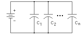
 Capacitors connected in parallel will add their capacitance together.
 Ctotal = C1 + C2 + ... + Cn
A parallel circuit is the most convenient way to increase the total storage of electric charge.
The total voltage rating does not change. Every capacitor will 'see' the same voltage. They all must be rated for at least the voltage of your power supply. Conversely, you must not apply more voltage than the lowest voltage rating among the parallel capacitors.
Series Capacitors
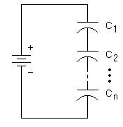
 Capacitors connected in series will have a lower total capacitance than any single one in the circuit.
 If you have only two capacitors in series this equation can be simplified to:
 If you have two identical capacitors in series this is further simplified to:
Caution: If the capacitors are different, the voltage will divide itself such that smaller capacitors hog more of the voltage! This is because they all get the same charging current, and voltage is inversely proportional to capacitance.
Worse yet, if one capacitor is slightly leaky, it will gradually transfer its voltage to the others, possibly exceeding their voltage rating in turn. And if one of them punches through its dielectric barrier, it can then damage others in a cascading fashion. This is why series capacitors are generally avoided in power circuits.
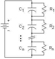
Resistor Network for Series Capacitors
But the series network is just too attractive when you have limited money and scavenged parts. How can you build in some safety? When you connect capacitors in series, any variance in values causes each one to charge at a different rate and to a different voltage. The variance can be quite large for electrolytics. On top of that, once the bank is charged, each capacitor's leakage current also causes a *different* voltage across each capacitor.
 If you charge a series bank up all the way, some caps are always undercharged and some overcharged (not good). To help them share voltage equally, you add balancing resistors. Basically they act like a big voltage divider and counteract the effects of variance in capacitance and leakage current. And if there is no leakage current, the capacitors must eventually become charged according to the voltage divider values.
Use this equation from p.13 of this excellent guide provided by Cornell Dubilier, "Aluminum Electrolytic Capacitor Application Guide" to calculate balancing resistors:
| For 2 capacitors in series: | R = (2Vm - Vb) / (0.0015 C Vb) |
| For N > 2 capacitors: | R = (NVm - Vb) / (0.0015 C Vb) |
| where | R = resistance in megohms Vm = max voltage you'll permit on either capacitor Vb = max voltage across the entire bank of two (or N) capacitors N = number of caps in series C = capacitance in microfarads |
Solution: R = (2x125 - 200) / (0.0015 x 1000 x 200) = 50/300 = 0.167 M = 167 K ohms
Some related consequences in this example are...
- The resistors in this example will put a load of I = 200v/(2*167K) = 0.6mA on the charging system. No problem here, this is most likely negligible to a high-power coilgun charging system.
- The balancing resistors will trickle down the cap's charge with an RC time constant of 2min 47sec, which imeans you should keep the charger connected right up until you fire. They act as a safety 'bleeder' resistor, which ensures that the caps don't remain charged the next day (or week or month!). Also, it prevents the capacitors charging themselves up to a few volts due to the dielectric memory effect.
- Each resistor will generate heat (P = I2R) in this example of 60mW nominal, 120 mW worst case. So you should use a 1-watt resistor, or larger. Okay, a 1/2-watt resistor would work too but it may get quite warm.
- The term "0.0015 C Vb" is an estimate (in microamps) of the difference in leakage currents in two capacitors in series at the rated temperature.
- A bad capacitor with leakage current more than about 1 mA is going to over-charge the other cap. So be careful, and periodically check the actual voltages!
- A bad capacitor with an internal short is going to over-charge the other capacitors (unless it fails open) regardless of what resistors you use.
Total Energy of Series vs. Parallel
Let's see whether a series or parallel circuit can store more total energy.Recall that energy in a single capacitor is proportional to the square of the voltage. It is tempting to use series capacitors to gain an energy boost by using 'voltage squared' to our advantage. But let's take a closer look...
Assume you have two identical capacitors, of capacitance C and voltage rating V. (The capacitors wouldn't have to be identical but the results are valid for the general case, and the math is much easier this way.) Let's calculate stored energy E for both circuits.
- Stored energy in two parallel capacitors, charged to voltage V:

- Stored energy in two series capacitors, charged to voltage 2V:

Conclusions
Parallel capacitors are safer and more reliable than series connections.There is no advantage in total energy storage to choose one of these circuits over another. But! There may well be a time when you need lower capacitance (e.g. a faster timing pulse) than your parts on hand can provide.
No comments:
Post a Comment